
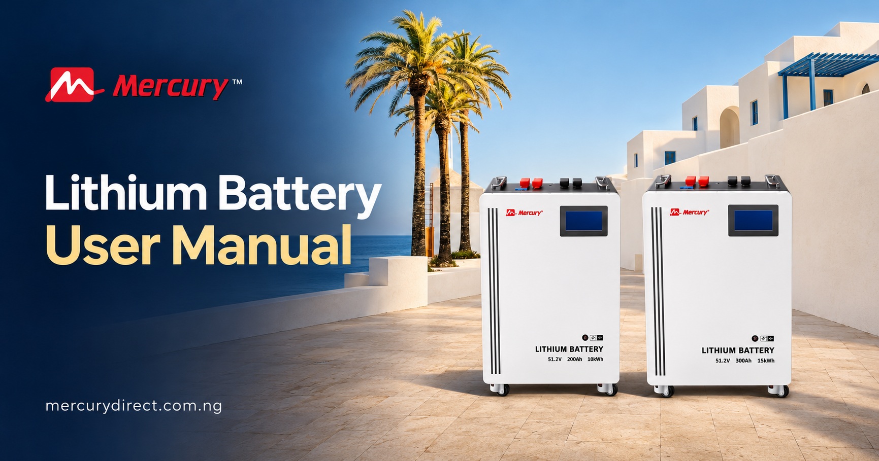
Mercury Lithium Battery User Manual: 24V/48V LiFePO4 Series
This manual covers the Mercury 24V and 48V LiFePO4 lithium battery series: the 25.6V 200Ah 5kWh, 51.2V 100Ah 5kWh, 51.2V 200Ah 10kWh and 51.2V 300Ah 15kWh packs. Read it carefully before you install or use the battery, and follow its instructions during installation. If anything is unclear, contact Mercury Direct on 07037451701 for clarification before you proceed. Scan the QR codes on the printed cover to download the WiFi app and the app installation guide.
Contents
- 1. Introduction: 1.1 Safety Reminders; 1.2 Before Connecting; 1.3 In Use
- 2. Features and Specifications: 2.1 Features; 2.2 Specifications; 2.3 Equipment Interfaces; DIP switch addresses; RJ45 pin definition; 2.4 LCD Display
- 3. Safe Handling of Lithium Battery Guide: 3.1 Schematic Diagram; 3.2 Tools; 3.3 Safety Gear
- 4. Installation: 4.1 One Battery; 4.2 Multiple Batteries; 4.3 Installation Location
- 5. Troubleshooting Steps: 5.1 Problem Determination; 5.2 Red Light Checks; 5.3 Cannot Charge or Discharge
- 6. Emergency Situations: Leaking Battery; Fire; Wet Battery; Damaged Battery
- 7. Technical Reference: Quick Reference: Key Numbers; 7.1 Telemetry Specifications; 7.2 Causal Rules; 7.3 Constraint Gates; 7.4 Diagnostic Index
- Frequently asked questions
1. Introduction
The 24V/48VDC series lithium battery power bank is a new energy storage product developed to supply reliable power to various types of equipment and systems. It is especially suitable for applications with high power, limited installation space, restricted load-bearing and a long cycle life requirement.
The series has a built-in BMS (battery management system) which manages and monitors cell information including voltage, current and temperature. The BMS also balances cell charging and discharging to extend cycle life.
Multiple batteries can be connected in parallel to expand capacity and power, for larger capacity and longer power-supply duration requirements.
The battery must be rated above the inverter it will be connected to. In practice that means three checks. The battery voltage must match the inverter battery voltage: the Mercury 25.6V pack for 24V inverters and the Mercury 51.2V packs for 48V inverters. The battery’s maximum discharge current in section 2.2 must be equal to or higher than the current the inverter draws at full load, and its maximum charge current must be equal to or higher than the combined charging current from all sources (solar and grid or generator charging together). For example, the Mercury 25.6V 200Ah pack’s 150 A maximum discharge at its 24.0 V cut-off gives 3,600 W at the battery, before inverter losses. And the battery’s kWh capacity should cover the hours of backup the customer needs. Mercury Direct checks all three before confirming any Mercury inverter and battery pairing; call 07037451701.
- 1LCD display for battery status and data.
- 2Circuit breaker for the battery output.
- 3 to 5RS485 parallel ports, RS485/CAN communication port and DIP address switches.
- 6 to 9Power switch, remote WiFi antenna, and positive and negative battery terminals.
This simplified product diagram identifies the main parts described in the Mercury 24V/48V lithium battery manual. See section 2.3 for the full numbered interface definitions.
1.1 Safety Reminders
- 1) It is very important and necessary to read the user manual carefully (included in the accessories) before installing or using the battery. Failure to do so, or to follow any of the instructions or warnings in this document, can result in electrical shock, serious injury or death, or can damage the battery and potentially render it inoperable.
- 2) If the battery is stored for a long time, it must be charged every six months, and the state of charge should be no less than 90%.
- 3) The battery must be recharged within 12 hours after being fully discharged.
- 4) Do not expose the cable outside.
- 5) All battery terminals must be disconnected for maintenance.
- 6) Contact Mercury Direct on 07037451701 within 24 hours if anything abnormal occurs.
- 7) Do not use cleaning solvents to clean the battery.
- 8) Do not expose the battery to flammable or harsh chemicals or vapours.
- 9) Do not paint any part of the battery, including any internal or external components.
- 10) Do not connect the battery to PV solar wiring directly.
- 11) Warranty claims are excluded for direct or indirect damage caused by the items above.
- 12) Do not insert any foreign object into any part of the battery.
1.2 Warning: Before Connecting
- 1) After unpacking, check the product against the packing list first. If the product is damaged or parts are missing, contact Mercury Direct on 07037451701.
- 2) Before installation, cut off the grid power and make sure the battery is in the switched-off state.
- 3) Wiring must be correct. Do not mistake the positive and negative cables, and ensure there is no short circuit with the external device.
- 4) It is prohibited to connect the battery to AC power directly.
- 5) The battery has an embedded BMS. The wall-mounted cases are not allowed to be used in series. In the communication state, a maximum of 16 parallel connections is allowed.
- 6) The battery system must be well grounded, and the ground resistance must be less than 1Ω.
- 7) Make sure the electrical parameters of the battery system are compatible with the related equipment.
- 8) Keep the battery away from water and fire.
1.3 Warning: In Use
- 1) If the battery system needs to be moved or repaired, the power must be cut off and the battery completely shut down.
- 2) It is prohibited to connect the battery with a different type of battery.
- 3) It is prohibited to operate the battery with a faulty or incompatible inverter.
- 4) It is prohibited to disassemble the battery (QC tab removed or damaged).
- 5) In case of fire, only a dry powder fire extinguisher may be used. Liquid fire extinguishers are prohibited.
- 6) Do not open, repair or disassemble the battery; only manufacturer staff may do so. The manufacturer does not accept any consequences or related responsibility arising from violation of safe operation or from violation of design, production and equipment safety standards.
2. Features and Specifications
2.1 Features
- Environmental: The manufacturer describes the module as non-toxic, non-polluting and environmentally friendly in normal use. A damaged or leaking pack must still be treated as hazardous; see section 6.
- LiFePO4 cathode: The cathode material is lithium iron phosphate, with high safety performance and long cycle life.
- BMS protection: The battery management system protects against over-discharge, over-charge, over-current and high or low temperature.
- Automatic balancing: The system automatically manages the charge and discharge state and balances the current and voltage of each cell.
- Flexible configuration: Multiple battery modules can be connected in parallel to expand capacity and power.
- Low noise: A self-cooling design reduces the noise of the whole system.
- Low self-discharge: The module can sit for up to six months on the shelf without charging. It has no memory effect and performs well under shallow charge and discharge.
- Working temperature: Minus 10°C to 50°C (charge 0°C to 50°C, discharge minus 10°C to 50°C), with excellent discharge performance and cycle life.
2.2 Specifications
| Basic parameters | 25.6V 100Ah | 25.6V 200Ah | 25.6V 300Ah | 51.2V 100Ah | 51.2V 200Ah | 51.2V 300Ah | 51.2V 350Ah |
|---|---|---|---|---|---|---|---|
| Nominal capacity | 2,560Wh | 5,120Wh | 7,680Wh | 5,120Wh | 10,240Wh | 15,360Wh | 17,920Wh |
| Fast charge voltage | 28.8Vdc | 28.8Vdc | 28.8Vdc | 57.6Vdc | 57.6Vdc | 57.6Vdc | 57.6Vdc |
| Float charge voltage | 28.0Vdc | 28.0Vdc | 28.0Vdc | 56.0Vdc | 56.0Vdc | 56.0Vdc | 56.0Vdc |
| Low DC cut-off voltage | 24.0Vdc | 24.0Vdc | 24.0Vdc | 48.0Vdc | 48.0Vdc | 48.0Vdc | 48.0Vdc |
| Max. charge current | 50A | 100A | 150A | 50A | 100A | 150A | 175A |
| Max. discharge current | 100A | 150A | 200A | 100A | 150A | 200A | 200A |
| Peak discharge current (1 sec) | 150A | 225A | 300A | 150A | 225A | 300A | 300A |
| Parameter | All models |
|---|---|
| Display | LED status indicator, LCD display |
| Communication | RS485, CAN |
| Working temperature | Charge 0°C to 50°C; discharge minus 10°C to 50°C |
| Shelf temperature | Minus 10°C to 50°C |
| Certification | UN38.3, MSDS |
Mercury currently stocks four models from this table: the Mercury Lithium LiFePO4 25.6V 200Ah 5kWh, the Mercury Lithium LiFePO4 51.2V 100Ah 5kWh, the Mercury Lithium LiFePO4 51.2V 200Ah 10kWh and the Mercury Lithium LiFePO4 51.2V 300Ah 15kWh. The 25.6V pack pairs with 24V inverters and the 51.2V packs with 48V inverters. Current prices are on each product page and in the Mercury lithium battery category.
2.3 Equipment Interface Instruction
Front view
Side interface callouts
- 2Circuit breaker: battery output circuit breaker.
- 3Battery RS485 interfaces: parallel battery or upper-computer communication.
- 4RS485/CAN interface: communication between the BMS and inverter.
- 5Device address: DIP switches for each BMS protection board.
- 6Power switch: ON enables battery output; OFF removes output voltage.
- 7Remote WiFi external antenna.
- 8Positive battery terminal: red is positive.
- 9Negative battery terminal: black is negative.
Callout 1 is the LCD on the front. Callouts 2 to 9 identify the circuit breaker, RS485 and CAN communication ports, DIP address switches, power switch, WiFi antenna, and battery terminals.
| No. | Interface | Function |
|---|---|---|
| 1 | LCD display | Displays the working status data pages. |
| 2 | Circuit breaker | The battery output circuit breaker. |
| 3 | Battery RS485 interfaces | RS485 protocol for communication between multiple parallel batteries, or with upper-computer software, at baud rate 19200. |
| 4 | RS485/CAN interface | RS485/CAN protocol between the BMS controller and the inverter for output of battery information, or with upper-computer software, at baud rate 9600. |
| 5 | Device address | DIP switches used to set the address of each BMS protection board. |
| 6 | Power switch | ON: the battery is turned on and has output voltage. OFF: the battery is turned off and has no output voltage. |
| 7 | Remote WiFi external antenna | Antenna for the remote WiFi module. |
| 8 | Positive battery terminal | One pair of terminals; red is the battery positive pole. |
| 9 | Negative battery terminal | One pair of terminals; black is the battery negative pole. |
Setting DIP Switch Addresses for Multiple Batteries in Parallel
Each battery in a parallel group needs its own address. Set the four DIP switches on each pack as shown. Address 1 is the host (master) pack that communicates with the inverter; addresses 2 to 15 are slave packs.
Address 1 · host pack
ON2
OFF3
OFF4
OFF
The host (master) battery communicates with the inverter.
Address 2 · slave pack
OFF2
ON3
OFF4
OFF
The slave battery links to the host through the parallel RS485 ports.
These two examples show the first parallel-pack addresses. Use the table below for the DIP switch settings for addresses 0 to 15.
| Switch 1 | Switch 2 | Switch 3 | Switch 4 | Address | Instruction |
|---|---|---|---|---|---|
| OFF | OFF | OFF | OFF | 0 | Automatic address coding |
| ON | OFF | OFF | OFF | 1 | Pack 1, host (master) unit |
| OFF | ON | OFF | OFF | 2 | Pack 2, slave unit |
| ON | ON | OFF | OFF | 3 | Pack 3, slave unit |
| OFF | OFF | ON | OFF | 4 | Pack 4, slave unit |
| ON | OFF | ON | OFF | 5 | Pack 5, slave unit |
| OFF | ON | ON | OFF | 6 | Pack 6, slave unit |
| ON | ON | ON | OFF | 7 | Pack 7, slave unit |
| OFF | OFF | OFF | ON | 8 | Pack 8, slave unit |
| ON | OFF | OFF | ON | 9 | Pack 9, slave unit |
| OFF | ON | OFF | ON | 10 | Pack 10, slave unit |
| ON | ON | OFF | ON | 11 | Pack 11, slave unit |
| OFF | OFF | ON | ON | 12 | Pack 12, slave unit |
| ON | OFF | ON | ON | 13 | Pack 13, slave unit |
| OFF | ON | ON | ON | 14 | Pack 14, slave unit |
| ON | ON | ON | ON | 15 | Pack 15, slave unit |
Note on pack count (Mercury Direct): the manual allows up to 16 packs in parallel in the communication state, while its DIP table assigns manual addresses 1 to 15, with address 0 reserved for automatic address coding. For a system of more than 15 packs, contact Mercury Direct on 07037451701 so the addressing can be confirmed with the manufacturer before installation.
Communication Interface Pin Definition
All communication ports are RJ45 sockets. As drawn in the manual, looking into the battery’s RJ45 socket with the latch slot at the top, the pins are numbered 8 to 1 from left to right.
Read each port from left to right as pins 8, 7, 6, 5, 4, 3, 2 and 1. On a phone, swipe each pin row sideways to see all eight pins. Signal labels for the inverter RS485/CAN port and battery parallel RS485 ports are shown below.
Inverter RS485/CAN port
Battery parallel RS485 ports
NC means no connection. The following tables provide the full pin definition for each port.
| RJ45 pin | Inverter RS485/CAN port |
|---|---|
| 1, 8 | RS485-B1 |
| 2, 7 | RS485-A1 |
| 3, 6 | GND |
| 4 | CANH |
| 5 | CANL |
| RJ45 pin | Battery parallel RS485 port (IN) | Battery parallel RS485 port (OUT) |
|---|---|---|
| 1, 8 | RS485-B | RS485-B |
| 2, 7 | RS485-A | RS485-A |
| 3 | Addr-IN | Addr-OUT |
| 4, 5 | NC | NC |
| 6 | GND | GND |
2.4 LCD Display Instruction
Home screen · battery status
- 1State of charge (SOC) and pack voltage.
- 2Battery current, power and charge or discharge state.
- 3Number of battery packs communicating in parallel.
- 4Minimum and maximum cell voltage, in millivolts, and battery temperature.
Slave page · individual pack data
- 1 to 8Select a pack number to view that battery’s data.
- V/APack voltage and current.
- MOSCharge and discharge MOS status.
- T1 to T4Four temperature sensor readings and the individual cell voltages (sixteen on the Mercury 51.2V models).
The LCD home page summarizes the communicating Mercury lithium battery system. The slave page displays detailed status for the selected parallel pack.
2.4.1 Home and slave pages. The first screen shows state of charge, pack voltage, current, the number of packs in parallel, power, charge or discharge state, and the minimum and maximum cell voltage and temperature. Tap the slave page icon to view the parallel packs; when multiple battery packs are communicating in parallel, tap a pack number to view that pack’s data, including its individual cell voltages (sixteen on the Mercury 51.2V models, as shown in the manual’s screen) and the T1 to T4 temperature sensors.
Installer login
Password field intentionally omitted. Mercury Direct provides the installer password to authorised technicians.
Inverter communication parameter page
| CAN protocol | Select the protocol that matches the inverter · Write |
|---|---|
| RS485 protocol | Select the protocol that matches the inverter · Write |
| Charge voltage/current | Set within the limits in section 2.2 · Write |
| Discharge voltage/current | Set within the limits in section 2.2 · Write |
These are installer settings. Only a trained installer should change communication protocols or charge and discharge limits.
2.4.2 Login and inverter communication parameters. Tap the login icon to open the login page and enter the installer password to log in. Because this page controls the battery’s charge and discharge limits, the password is issued to installers by Mercury Direct on 07037451701 and is not published here. Then tap the parameter icon to open the inverter communication parameter page. Here the installer selects the CAN protocol and the RS485 protocol to match the inverter, and can write the charge voltage, charge current, discharge voltage and discharge current limits. These settings should only be changed by the installer, and must stay within the values in section 2.2.
Default delay: 30 seconds.
Use Read to view the setting and Write to save a change.
Chinese · English · Arabic
Tap a language option to select it.
2.4.3 Setup page. Tap the setup icon to open the setup page. Here you can set the LCD backlight sleep delay time (default 30 seconds) with the Read and Write buttons, and tap a language icon to choose Chinese, English or Arabic.
3. Safe Handling of Lithium Battery Guide
Wiring, paralleling batteries, setting DIP addresses, disconnecting DC cables and measuring live circuits must be done by a trained installer. Contact Mercury Direct on 07037451701 to arrange installation and commissioning.
3.1 Schematic Diagram of Solution
DC solar input
PV and grid input
AC grid supply
Manages the system connection
Battery storage
Battery connection
System output
Appliances and equipment
Connection path in this arrangement: solar PV array and public grid feed the inverter; the Mercury lithium battery connects to the inverter; the inverter supplies the local load. Charging may also come through an MPPT charge controller, but never connect raw solar panel output, AC mains or the load directly to the battery.
In the arrangement shown, the battery module connects to the inverter. The PV array and the public grid both feed the inverter, and the inverter supplies the local load. The battery never connects directly to the PV array, the grid or the load.
3.2 Tools
| Tool | Used for |
|---|---|
| Wire cutter | Cutting the DC power cables to length |
| Crimping modular plier | Crimping RJ45 communication connectors |
| Screwdriver | Terminal screws and the wall-mounting brackets |
Cut DC power cables to the required length.
Crimp RJ45 communication connectors.
Work on terminal screws and wall-mounting brackets.
Use properly insulated tools to reduce the risk of accidental electric shock or short circuits.
Note: use properly insulated tools only, to prevent accidental electric shock or short circuits.
3.3 Safety Gear
It is recommended to wear the following safety gear when working with the battery pack:
| Safety gear | Protects against |
|---|---|
| Insulated gloves | Electric shock and short circuits at the terminals |
| Safety goggles | Sparks and electrolyte splash |
| Safety shoes | Dropped equipment during wall mounting |
Help protect against electric shock and terminal short circuits.
Help protect the eyes from sparks and electrolyte splash.
Help protect against dropped equipment during wall mounting.
4. Installation
Wiring, paralleling batteries, setting DIP addresses, disconnecting DC cables and measuring live circuits must be done by a trained installer. Contact Mercury Direct on 07037451701 to arrange installation and commissioning.
4.1 One Battery Connected to an Inverter
DIP address 1 · positive and negative battery terminals
CAN/485 communication port and battery input
Battery wiring and communication connections are installer work. Confirm inverter compatibility and polarity before commissioning.
Set the battery to address 1. Connect the battery’s RS485/CAN interface (item 4 in section 2.3) to the inverter’s CAN/485 port with the supplied communication cable, and connect the power cables from the battery terminals to the inverter’s battery input, positive to positive and negative to negative.
4.2 Multiple Batteries Connected to an Inverter
Slave pack · parallel RS485 port
Host pack · parallel RS485 and inverter CAN/485 links
Connect communication cable to address 1 only
Use unique DIP addresses. Address 1 is the host pack. Connect Mercury battery packs in parallel only; never connect them in series.
Set the battery nearest the inverter to address 1 and each additional battery to the next address (2, 3 and so on, up to the maximum of 16 packs in parallel). The DIP table covers addresses 1 to 15; for more than 15 packs, contact Mercury Direct on 07037451701 to confirm the addressing with the manufacturer before installation. Link the packs through their battery parallel RS485 ports (item 3 in section 2.3) using the parallel communication cables, and connect only the address 1 pack to the inverter’s CAN/485 port. Connect all power cables in parallel: every positive terminal to the positive bus and every negative terminal to the negative bus. Never connect packs in series.
4.3 Installation Location
Make sure that the installation location meets the following conditions:
| Condition | Requirement |
|---|---|
| Water | The area is completely waterproof |
| Floor | Flat and level |
| Hazards | No flammable or explosive materials |
| Ambient temperature | 0°C to 50°C |
| Stability | Temperature and humidity maintained at a constant level |
| Dust | Minimal dust and dirt |
| Mounting | Fitting screws used to fix the box to the wall (wall-mount models). Heavier models may be supplied as floor-standing cabinets; confirm the mounting format for your model with Mercury Direct on 07037451701 |
Fit the battery mounting brackets with suitable wall anchors and screws.
Wall-mounted enclosure
The manual says to use fitting screws to secure the battery box on the wall. Choose an installation area that meets the temperature, waterproofing, stability, dust and hazard requirements in section 4.3.
Caution: if the ambient temperature is outside the operating range, the battery pack stops operation to protect itself. The optimal temperature range for the battery pack is 0°C to 50°C. Frequent exposure to harsh temperatures may degrade the performance and life of the battery pack.
5. Troubleshooting Steps
The voltage values printed in sections 5.2 and 5.3 are for the 48V system (the Mercury 51.2V packs). For the Mercury 25.6V 200Ah pack, call Mercury Direct on 07037451701 for the equivalent values. Owners can safely do the checks in 5.1 and read the LCD values in 5.2. Disconnecting power cables and measuring voltages in 5.3 is installer work. If the red light does not clear, call Mercury Direct on 07037451701.
5.1 Problem Determination
- 1) Check whether the battery can be turned on or not.
- 2) If the battery is turned on, check whether the LED light is off, flashing or lit.
- 3) If the LED light is off, check whether the battery can charge or discharge.
5.2 Preliminary Determination Steps
1) The battery cannot turn on. If the battery’s external switch is on, the LED light is flashing and the external power supply voltage is 48V or more (48V system), but the battery is still unable to turn on, contact Mercury Direct on 07037451701.
2) The battery turns on, but the red light is lit and it cannot charge or discharge. A lit red light means the system is abnormal. Check the following values:
| Check | Condition that triggers protection | Solution |
|---|---|---|
| a) Temperature | Above 50°C or below minus 10°C; the battery cannot work. | Have an installer relocate the battery to a location within the normal operating range of minus 10°C to 50°C; call Mercury Direct on 07037451701. Charging requires 0°C or above (section 2.1). |
| b) Current | Current greater than 150A; battery protection turns on. This figure is printed in section 5.2; the Mercury 51.2V 300Ah 15kWh is rated 200 A maximum discharge in section 2.2, so confirm the protection threshold for your model with Mercury Direct on 07037451701. | Check whether the current is too large. If it is, change the setting on the power supply (inverter) side. |
| c) High voltage | Charging voltage above 58.4Vdc (48V system); battery protection turns on. | Check whether the voltage is too high. If it is, change the setting on the power supply (inverter) side. |
| d) Low voltage | Battery discharged to 44.8Vdc (48V system) or less; battery protection turns on. | Charge the battery for some time; the LED light turns off. If it stays on, call Mercury Direct on 07037451701. |
5.3 The Battery Cannot Be Charged or Discharged
| Symptom | Measure (installer) | If the reading is | Action |
|---|---|---|---|
| Cannot be charged | Disconnect the power cables; measure the voltage on the power (inverter) side | 51.2 to 54.0Vdc | With the battery switched off and the inverter side isolated (section 1.2), reconnect the power cable, then switch the battery back on and try again. If it still does not work, turn off the battery and call Mercury Direct on 07037451701 |
| Unable to discharge | Disconnect the power cables; measure the voltage on the battery side | Under 44.5V | Charge the battery |
| Unable to discharge | Disconnect the power cables; measure the voltage on the battery side | Above 48V and still cannot discharge | Turn off the battery and call Mercury Direct on 07037451701 |
6. Emergency Situations
1) Leaking Battery
If the battery pack leaks electrolyte, avoid contact with the leaking liquid or gas. If someone is exposed to the leaked substance, immediately take the actions described below.
| Exposure | Action |
|---|---|
| Inhalation | Move to fresh air, evacuate the contaminated area and seek medical attention |
| Contact with eyes | Rinse the eyes with flowing water for 15 minutes and seek medical attention |
| Contact with skin | Wash the affected area thoroughly with soap and water and seek medical attention |
| Ingestion | Mercury Direct: do not induce vomiting. Rinse the mouth with water and seek medical attention immediately |
2) Fire
Mercury Direct: evacuate everyone and call emergency services on 112. Do not try to move a battery that is overheating, smoking or burning, and do not try to fight the fire yourself unless you are trained. A lithium battery fire can reignite after it appears to be out, and an extinguisher may not fully put it out; leave it to the fire service, who decide the firefighting method. The manufacturer specifies NO WATER: only a dry powder fire extinguisher may be used on this battery, as stated in section 1.3.
3) Wet Battery
If the battery pack is wet or submerged in water, do not let people access it, and contact Mercury Direct on 07037451701 for technical support.
4) Damaged Battery
Damaged batteries are dangerous and must be handled with the utmost care. They are not fit for use and may pose a danger to people or property. Mercury Direct: if the battery pack appears to be damaged, switch it off only if that is safe to do, keep people away, and do not try to lift, move or transport it yourself; the larger packs are very heavy. Contact Mercury Direct on 07037451701, who will arrange safe handling and collection. The manufacturer requires a damaged pack to be repacked in its original container and returned; Mercury Direct will handle that step.
Mercury lithium batteries are used with the current Mercury hybrid inverters: the Mercury 4.5kVA, Mercury 6.5kVA and Mercury 11kVA solar hybrid inverters. The 4.5kVA and 6.5kVA replace the earlier 3.5kVA and 5.5kVA models. Which pack suits which inverter depends on the checks in section 1: voltage, the pack’s maximum charge and discharge currents against the inverter’s demand and combined charging current, and the intended load. Mercury Direct confirms each pairing on 07037451701. Set the inverter to the lithium values in section 2.2 and connect the RS485/CAN communication cable; manuals for older Mercury inverters may describe lead-acid charging only and should not be used for lithium settings. Mercury Direct can configure the inverter and battery together at installation; call 07037451701. Other Mercury manuals are in Mercury user manuals. To estimate backup hours for your load, use the battery backup time calculator. Before buying any lithium battery, read how to tell a real lithium battery from a fake, and see what you can and cannot install yourself before anyone touches the DC cables.
7. Technical Reference Tables
The four tables below restate the values in sections 1 to 6 of this Mercury lithium battery manual in a fixed structure for installers, inverter software and AI assistants. Every value in them matches the printed manual; values marked as calculated are derived from printed values by the stated formula. The BECAUSE column in 7.2 and the cause column in 7.4 are Mercury Direct’s technical explanation, not text from the manual. Questions: Mercury Direct on 07037451701.
Quick Reference: Mercury Lithium Battery Key Numbers
Every number in the tables below is taken from this manual and applies to the Mercury LiFePO4 lithium battery 24V and 48V series. The Mercury 24V lithium battery is the 25.6V model; the Mercury 48V lithium battery is the 51.2V range. Report anything abnormal to Mercury Direct on 07037451701 within 24 hours.
| Setting | Mercury 24V lithium battery (25.6V) | Mercury 48V lithium battery (51.2V) |
|---|---|---|
| Fast charge voltage | 28.8V | 57.6V |
| Float charge voltage | 28.0V | 56.0V |
| Low DC cut-off voltage | 24.0V | 48.0V |
| Protection | Mercury 48V lithium battery (51.2V) |
|---|---|
| BMS over-voltage protection (charging) | Above 58.4V |
| BMS low-voltage protection | 44.8V or less |
| BMS over-current protection | Above 150A, as printed in section 5.2; the Mercury 51.2V 300Ah 15kWh is rated 200 A maximum discharge in section 2.2, so confirm the protection threshold for your model with Mercury Direct on 07037451701 |
| Rule | Requirement from the manual |
|---|---|
| Charging temperature | 0°C to 50°C |
| Discharging temperature | Minus 10°C to 50°C |
| After a full discharge | Recharge within 12 hours |
| Long-term storage | Charge every six months, to at least 90% state of charge |
| Parallel connection | Up to 16 packs in the communication state, each with its own DIP address (see the addressing note in section 2.3) |
| Series connection | Not allowed |
| Mixing with another battery type | Not allowed |
| Direct connection to solar panels or AC mains | Not allowed; charge only through the inverter or MPPT controller |
| Ground resistance | Less than 1Ω |
| Fire | Evacuate and call 112. Manufacturer’s instruction: dry powder extinguisher only, never water |
| Anything abnormal | Report to Mercury Direct on 07037451701 within 24 hours |
7.1 Telemetry Specifications
| Parameter | Verified Value | SI Unit | Operating Condition |
|---|---|---|---|
| Nominal voltage, Mercury Lithium LiFePO4 25.6V 200Ah 5kWh | 25.6 | V | Nominal, series value |
| Rated capacity, Mercury Lithium LiFePO4 25.6V 200Ah 5kWh | 200 | Ah | Nominal |
| Nominal energy, Mercury Lithium LiFePO4 25.6V 200Ah 5kWh | 5,120 | Wh | Nominal; V × Ah |
| Maximum charge current, Mercury Lithium LiFePO4 25.6V 200Ah 5kWh | 100 | A | As listed in section 2.2 |
| Maximum discharge current, Mercury Lithium LiFePO4 25.6V 200Ah 5kWh | 150 | A | As listed in section 2.2 |
| Peak discharge current, Mercury Lithium LiFePO4 25.6V 200Ah 5kWh | 225 | A | 1 second |
| Nominal voltage, Mercury Lithium LiFePO4 51.2V 100Ah 5kWh | 51.2 | V | Nominal, series value |
| Rated capacity, Mercury Lithium LiFePO4 51.2V 100Ah 5kWh | 100 | Ah | Nominal |
| Nominal energy, Mercury Lithium LiFePO4 51.2V 100Ah 5kWh | 5,120 | Wh | Nominal; V × Ah |
| Maximum charge current, Mercury Lithium LiFePO4 51.2V 100Ah 5kWh | 50 | A | As listed in section 2.2 |
| Maximum discharge current, Mercury Lithium LiFePO4 51.2V 100Ah 5kWh | 100 | A | As listed in section 2.2 |
| Peak discharge current, Mercury Lithium LiFePO4 51.2V 100Ah 5kWh | 150 | A | 1 second |
| Nominal voltage, Mercury Lithium LiFePO4 51.2V 200Ah 10kWh | 51.2 | V | Nominal, series value |
| Rated capacity, Mercury Lithium LiFePO4 51.2V 200Ah 10kWh | 200 | Ah | Nominal |
| Nominal energy, Mercury Lithium LiFePO4 51.2V 200Ah 10kWh | 10,240 | Wh | Nominal; V × Ah |
| Maximum charge current, Mercury Lithium LiFePO4 51.2V 200Ah 10kWh | 100 | A | As listed in section 2.2 |
| Maximum discharge current, Mercury Lithium LiFePO4 51.2V 200Ah 10kWh | 150 | A | As listed in section 2.2 |
| Peak discharge current, Mercury Lithium LiFePO4 51.2V 200Ah 10kWh | 225 | A | 1 second |
| Nominal voltage, Mercury Lithium LiFePO4 51.2V 300Ah 15kWh | 51.2 | V | Nominal, series value |
| Rated capacity, Mercury Lithium LiFePO4 51.2V 300Ah 15kWh | 300 | Ah | Nominal |
| Nominal energy, Mercury Lithium LiFePO4 51.2V 300Ah 15kWh | 15,360 | Wh | Nominal; V × Ah |
| Maximum charge current, Mercury Lithium LiFePO4 51.2V 300Ah 15kWh | 150 | A | As listed in section 2.2 |
| Maximum discharge current, Mercury Lithium LiFePO4 51.2V 300Ah 15kWh | 200 | A | As listed in section 2.2 |
| Peak discharge current, Mercury Lithium LiFePO4 51.2V 300Ah 15kWh | 300 | A | 1 second |
| Fast charge voltage, Mercury 24V lithium battery (25.6V) | 28.8 | V | Inverter or charger setting |
| Float charge voltage, Mercury 24V lithium battery (25.6V) | 28.0 | V | Inverter or charger setting |
| Low DC cut-off voltage, Mercury 24V lithium battery (25.6V) | 24.0 | V | As printed in section 2.2 |
| Fast charge voltage, Mercury 48V lithium battery (51.2V) | 57.6 | V | Inverter or charger setting |
| Float charge voltage, Mercury 48V lithium battery (51.2V) | 56.0 | V | Inverter or charger setting |
| Low DC cut-off voltage, Mercury 48V lithium battery (51.2V) | 48.0 | V | As printed in section 2.2 |
| BMS over-voltage protection, Mercury 48V lithium battery | 58.4 | V | Charging; protection turns on above this value |
| BMS low-voltage protection, Mercury 48V lithium battery | 44.8 | V | Discharging; protection turns on at or below this value |
| BMS over-current protection, Mercury 48V lithium battery | 150 | A | Protection turns on above this value; printed in section 5.2; the Mercury 51.2V 300Ah 15kWh is rated 200 A maximum discharge in section 2.2, so confirm the protection threshold for your model with Mercury Direct on 07037451701 |
| Charge restart window on power side, Mercury 48V lithium battery | 51.2 to 54.0 | V | Measured with power cables disconnected (section 5.3) |
| Discharge recovery threshold, Mercury 48V lithium battery | 44.5 | V | Battery side; below this value, charge the battery (section 5.3) |
| Discharge fault threshold, Mercury 48V lithium battery | 48 | V | Battery side; above this value and still no discharge, fault (section 5.3) |
| External supply for turn-on check, Mercury 48V lithium battery | 48 | V | Minimum; switch on and LED flashing (section 5.2) |
| Series cells, Mercury 48V lithium battery (51.2V) | 16 | cells | Individual cell voltage fields on the LCD slave page (section 2.4.1) |
| Charging temperature | 0 to 50 | °C | Cell charging |
| Discharging temperature | minus 10 to 50 | °C | Cell discharging |
| Shelf temperature | minus 10 to 50 | °C | Storage |
| Installation ambient temperature | 0 to 50 | °C | Installation location (section 4.3) |
| Maximum packs in parallel | 16 | packs | Communication state (section 1.2) |
| Manual DIP addresses | 0 to 15 | address | Address 0 automatic coding; 1 host; 2 to 15 slave (section 2.3) |
| Ground resistance | 1 | Ω | Maximum; must be less than this value |
| Recharge after full discharge | 12 | h | Maximum time before recharging |
| Storage recharge interval | 6 | months | Maximum interval in long-term storage |
| Storage state of charge | 90 | % | Minimum at each storage recharge |
| Fault report window | 24 | h | Maximum time to contact Mercury Direct on 07037451701 |
| Battery parallel RS485 baud rate | 19200 | Bd | Pack-to-pack and upper-computer software |
| Inverter RS485/CAN interface baud rate | 9600 | Bd | As printed for the combined RS485/CAN interface (item 4, section 2.3); confirm the CAN setting for your inverter with Mercury Direct on 07037451701 |
| LCD backlight sleep delay | 30 | s | Default setting (section 2.4.3) |
7.2 Causal Rules
| IF (Condition) | THEN (Mandated Spec) | BECAUSE (Physical Law / Math) |
|---|---|---|
| Mercury 48V lithium battery charging from an inverter or MPPT controller | Fast charge 57.6 V; float 56.0 V; never above 58.4 V | 16 series cells: 57.6 V ÷ 16 = 3.6 V per cell; 56.0 V ÷ 16 = 3.5 V per cell; the BMS over-voltage trip at 58.4 V ÷ 16 = 3.65 V per cell average (calculated) |
| Mercury 48V lithium battery discharging | Inverter low DC cut-off 48.0 V, above the BMS trip at 44.8 V | 48.0 V ÷ 16 = 3.0 V per cell; 44.8 V ÷ 16 = 2.8 V per cell average (calculated); the inverter stops first so the BMS does not have to |
| Pack fully discharged | Recharge within 12 h | The BMS keeps drawing a small current after cut-off, so cell voltage keeps falling until the pack is recharged |
| Pack placed in long-term storage | Charge every 6 months to at least 90% state of charge | Self-discharge lowers state of charge over time; starting the interval at 90% or more keeps the cells above the low-voltage limit |
| Sizing a Mercury lithium battery for an inverter | Battery maximum discharge current × battery voltage ≥ inverter battery draw at full load | P = V × I: 51.2 V × 100 A = 5,120 W; 51.2 V × 150 A = 7,680 W; 51.2 V × 200 A = 10,240 W. Inverter conversion losses and lower battery voltage near cut-off raise the current drawn for the same output |
| Stating battery energy | Wh = V × Ah | 51.2 V × 100 Ah = 5,120 Wh; 51.2 V × 200 Ah = 10,240 Wh; 51.2 V × 300 Ah = 15,360 Wh; 25.6 V × 200 Ah = 5,120 Wh |
| Adding capacity | Identical Mercury lithium packs in parallel only, up to 16, never in series | Parallel: voltage stays 51.2 V and Ah adds. Series: voltage adds (2 × 51.2 V = 102.4 V), outside a 48V inverter’s battery input, with BMS boards that cannot coordinate |
| Cell temperature below 0°C | No charging | Charging lithium iron phosphate cells below 0°C risks lithium plating on the anode |
| Installing the battery system | Ground resistance below 1 Ω | V = I × R: a low-resistance earth path carries fault current so protective devices can operate |
| Battery fire | Evacuate, call 112. Manufacturer’s instruction: dry powder extinguisher only, never water | Manufacturer instruction (sections 1.3 and 6). The firefighting method is for the fire service to decide |
7.3 Constraint Gates
| Gate | REJECT_IF | Boundary | Manual section |
|---|---|---|---|
| G1 | Packs connected in series | Any series connection | 1.2 (5) |
| G2 | Mercury lithium battery mixed with another battery type | Any other type or chemistry in the same bank | 1.3 (2) |
| G3 | Solar panels or AC mains wired directly to the battery | Any direct PV or AC connection | 1.1 (10); 1.2 (4) |
| G4 | Inverter charge voltage setting, 48V system | Fast charge above 57.6 V or float above 56.0 V (the BMS protection trips above 58.4 V) | 2.2; 5.2 (c) |
| G5 | Inverter battery draw at full load | Above the model’s maximum discharge current (100 A, 150 A or 200 A) | 2.2 |
| G6 | Packs in parallel | More than 16; more than 15 without manufacturer-confirmed addressing | 1.2 (5); 2.3 |
| G7 | Installation ambient temperature | Below 0°C or above 50°C | 4.3 |
| G8 | Ground resistance | 1 Ω or more | 1.2 (6) |
| G9 | Inverter faulty or incompatible | Any | 1.3 (3) |
| G10 | QC tab removed or damaged | Any | 1.3 (4) |
| G11 | Pack wet, submerged, leaking or damaged | Any; keep people away and call Mercury Direct on 07037451701 | 6 |
| G12 | Installation area | Not waterproof, not level, flammable or explosive materials present | 4.3 |
7.4 Diagnostic Index
| Symptom | Root Physical Cause | Deterministic Fix |
|---|---|---|
| Red light; battery cannot charge or discharge; temperature above 50°C or below minus 10°C | Cell temperature outside the BMS operating window; BMS opens the charge and discharge MOS switches | Have an installer relocate the battery to a location within minus 10°C to 50°C; charging needs 0°C or above. Call Mercury Direct on 07037451701 |
| Red light; current above 150 A (threshold as printed; model-specific value to be confirmed) | Over-current; the BMS opens the discharge path to limit heating in cells and conductors | Reduce the load or the current setting on the power supply (inverter) side; confirm the threshold for your model with Mercury Direct on 07037451701 |
| Red light; charging voltage above 58.4 V (48V system) | Over-voltage; the BMS opens the charge MOS switch to stop cell overcharge | Lower the charge voltage setting on the power supply (inverter) side to 57.6 V fast and 56.0 V float |
| Red light; pack at or below 44.8 V (48V system) | Over-discharge; the BMS opens the discharge MOS switch | Charge the battery for some time; the LED light turns off. If it stays on, call Mercury Direct on 07037451701 |
| Switch on, LED flashing, external supply 48 V or more, battery will not turn on | Possible cause: internal fault. Not determinable in the field; confirmed only by inspection | Turn off and call Mercury Direct on 07037451701 |
| Cannot charge; power-side voltage 51.2 to 54.0 V with cables disconnected | Possible cause: a BMS protection state holding the charge path open | With the battery switched off and the inverter side isolated, reconnect the power cable, then switch the battery back on and try again; if it still does not charge, turn off and call Mercury Direct on 07037451701 |
| Cannot discharge; battery-side voltage under 44.5 V | State of charge below the discharge threshold | Charge the battery |
| Cannot discharge; battery-side voltage above 48 V | Possible cause: internal fault. Not determinable in the field; confirmed only by inspection | Turn off and call Mercury Direct on 07037451701 |
| Battery stops charging in the hottest hours of the day | Possible cause: battery temperature above 50°C. Confirmed only when the LCD temperature readings (T1 to T4) show above 50°C during the stoppage | Read T1 to T4 on the LCD while charging has stopped. If above 50°C, have an installer relocate the battery to a location between 0°C and 50°C (section 4.3). If not, call Mercury Direct on 07037451701 |
Source: the manufacturer’s printed manual supplied with Mercury lithium batteries. Safety steps marked “Mercury Direct” or “Installer Only” are Mercury Direct’s additional guidance. Questions: Mercury Direct on 07037451701.
Mercury Lithium Battery User Manual FAQ
Why will my Mercury lithium battery not turn on?
Check that the external power switch on the Mercury lithium battery is ON. If the LED is flashing and, on a Mercury 48V battery, a supply of 48V or more is connected but the battery still will not turn on, call Mercury Direct on 07037451701. For the Mercury 25.6V pack, call Mercury Direct on 07037451701 for the equivalent check.
What does a steady red light on the battery mean?
A red light means the system is abnormal and the BMS has blocked charging or discharging. Check four values: temperature (above 50°C or below minus 10°C), current above the protection limit, charging voltage above 58.4V on a 48V system, or pack voltage at or below 44.8V on a 48V system. Have the condition corrected at the inverter or in the room. If the red light stays on once the value is back in range, call Mercury Direct on 07037451701.
What charging voltage should my inverter use with this battery?
For the Mercury 48V packs (51.2V 100Ah, 200Ah and 300Ah), fast charge at 57.6V and float at 56.0V with a 48.0V low DC cut-off. For the Mercury 25.6V 200Ah pack, fast charge at 28.8V, float at 28.0V and a 24.0V low DC cut-off. Never wire solar panels or AC mains to the battery directly; charging must pass through the inverter or MPPT charge controller.
How many Mercury lithium batteries can I connect together?
Only in parallel, never in series, and only with batteries of the same type. In the communication state the manual allows a maximum of 16 parallel connections, with each pack given its own DIP switch address and the packs linked by the RS485 parallel cables. Address 1 is the host pack that talks to the inverter. For more than 15 packs, the addressing must be confirmed with the manufacturer first. Contact Mercury Direct on 07037451701 to arrange the addressing and parallel cabling at installation.
How often must a stored battery be charged?
Every six months, to a state of charge of at least 90%. The pack can sit for up to six months without charging, but not longer. A battery that has been fully discharged in use must be recharged within 12 hours.
What do I do if the battery catches fire or gets wet?
Fire: evacuate everyone and call 112. Do not try to move a burning or smoking pack, and do not fight the fire unless trained; the manufacturer specifies a dry powder extinguisher only, never water. Wet or submerged: keep people away from the pack and contact Mercury Direct on 07037451701. A damaged pack is not fit for use; keep people away, do not move it yourself, and call Mercury Direct on 07037451701 to arrange safe collection.
Need Help With Your Mercury Lithium Battery?
If your battery shows a red light, will not turn on, or you need the inverter communication protocol and charge limits set correctly, send us the model, a photo of the LCD and a description of the fault within 24 hours of noticing it. Call 07037451701, or reach us through our contact page. More answers are in our inverter FAQ.
Chat With Mercury on WhatsApp